
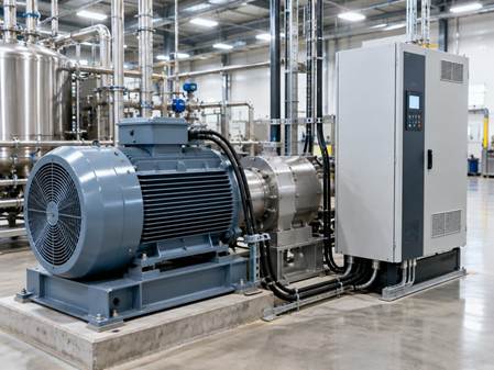
In the relentless pursuit of industrial efficiency and precision, modern motor control systems play a crucial role. Synchronous motors, especially when paired with Variable Frequency Drives (VFDs), stand out as a highly effective solution. These advanced systems offer significant energy savings and unparalleled operational accuracy across a wide range of applications.
This extensive guide will explore the unique characteristics of synchronous motor VFDs. We will delve into how they differ from their asynchronous counterparts and examine the sophisticated control strategies they employ. Our discussion will cover various VFD topologies, the intricacies of rotor excitation, and the substantial advantages these systems deliver, including enhanced efficiency and improved power factor correction.
Finally, we will address common challenges, such as retrofitting VFDs onto existing synchronous motors and navigating critical commissioning steps. Our goal is to provide you with a comprehensive understanding of this vital technology, equipping you to optimize industrial processes and drive sustainable operations in October 2026 and beyond.
The integration of VFDs with synchronous motors represents a significant leap in industrial automation, offering precise control and enhanced performance. Synchronous motors themselves are a diverse group, including traditional field-wound machines and modern permanent magnet synchronous motors (PMSM) or synchronous reluctance motors (SynRM). The choice of motor type, combined with the appropriate VFD topology, dictates the overall system’s capabilities, particularly in terms of torque density, efficiency, and total cost of ownership.
For instance, synchronous reluctance motors (SynRM) are gaining traction due to their impressive power and torque density, offering a 20–40 percent increase for the same insulation temperature class compared to induction motors. For smaller motors, like those at the 3 or 4 kW level, SynRM technology can even yield up to 60 percent more power for the same temperature rise. This performance comes without the reliance on rare-earth magnets, which can be expensive and vulnerable to supply chain disruptions, mitigating a key risk associated with some PMSM designs. However, the overall system cost must consider the VFD, which is often more sophisticated for synchronous machines.
Synchronous vs Asynchronous VFD Drive Dynamics
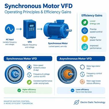
The fundamental difference between synchronous and asynchronous (induction) motor VFDs lies in how they manage rotor speed and flux. In a synchronous motor, the rotor’s speed is precisely locked to the rotating magnetic field of the stator, meaning there is zero slip. This inherent synchronization is a key advantage, ensuring consistent performance even under varying loads. When controlled by a VFD, synchronous motors achieve this precise speed regulation by adjusting the frequency and voltage of the power supplied to the stator.
Asynchronous motors, conversely, rely on a phenomenon called “slip” – the rotor always lags slightly behind the stator’s magnetic field – to induce current in the rotor and generate torque. While VFDs can control the speed of induction motors effectively by manipulating frequency, this slip inherently leads to rotor cage losses, contributing to energy inefficiency.
For synchronous motors, a VFD employs advanced control methods like flux vector control. In PMSMs, for example, the permanent magnets generate the flux, so the VFD’s primary role is to manage the torque-producing current component and factor in the motor’s back EMF constant. This is distinct from induction motors, where the VFD continuously controls both flux and torque currents across the entire speed range, as the flux is induced rather than inherent. This precise control allows synchronous VFDs to deliver high precision and maintain efficiency, particularly at partial loads where induction motors might see a greater drop in performance due to increased slip. The elimination of slip losses in synchronous motors can lead to efficiency gains ranging from approximately 0.6 percent for a 220 kW motor to a significant 8 percent for a 3 kW motor.
Here’s a comparison of their operating characteristics:
Feature Synchronous Motor VFD Asynchronous (Induction) Motor VFD Rotor Speed Control Rotor speed precisely locked to stator frequency (zero slip) Rotor speed lags stator frequency (requires slip) Flux Generation Permanent magnets or DC excitation on rotor Induced by stator field, requires slip Efficiency Higher, especially at partial loads; no slip losses Generally lower due to slip losses Power Factor Can operate at unity or leading power factor (VAR support) Typically lagging, though VFD can improve Control Complexity More complex, often requires rotor position feedback or advanced algorithms Simpler, standard VFDs are common Precision Excellent, ideal for constant speed/high precision Good, suitable for flexible speed control Typical Applications Robotics, power generation, compressors, large pumps Pumps, fans, conveyors, HVAC, general industrial drives Inverter Topologies and Rotor Field Excitation Control
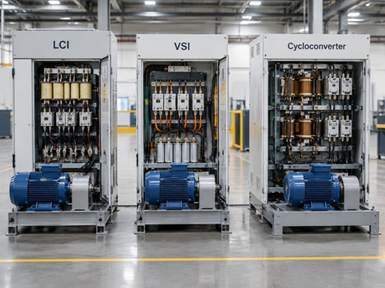
The choice of VFD topology is critical, especially for large synchronous motors. The main topologies include Load Commutated Inverters (LCIs), Voltage Source Inverters (VSIs), and cycloconverters.
Load Commutated Inverters (LCIs) are a mature and robust technology, often preferred for multi-megawatt (MW) synchronous motors, with systems available from 1 MW to over 100 MW. LCIs rely on the motor’s back electromotive force (EMF) for commutation, making them highly efficient at high power and speed. However, this dependence means an LCI cannot start a fully loaded synchronous motor from a complete standstill. The motor must first be accelerated to about 5–8% of its synchronous speed using a “pony motor” or a starting cage before the LCI can take over. The LCI then controls the motor by adjusting frequency and voltage, while also managing the rotor’s DC excitation.
Voltage Source Inverters (VSIs), particularly those employing IGBT (Insulated Gate Bipolar Transistor) technology, are becoming increasingly common for synchronous motors, especially PMSMs and SynRMs, across a wider power range. VSIs offer excellent dynamic performance and can provide precise control down to zero speed, making them suitable for applications requiring high torque at low speeds or frequent starts/stops. They achieve commutation internally, independent of the motor’s back EMF.
Cycloconverters are another topology, primarily used for very large, low-speed synchronous motors, such as those found in grinding mills. They directly convert AC line frequency to a variable lower frequency without an intermediate DC link, offering robust performance but typically at the expense of higher harmonic distortion and lower output frequency range.
A crucial aspect of controlling field-wound synchronous motors with VFDs is managing rotor excitation. This can be achieved through:
- Brush-type exciters: These use brushes and slip rings to supply DC current to the rotor windings. They offer fast response times (50–100 ms) for excitation control. For retrofits, retaining a healthy existing brush-type exciter is often more practical than replacing it.
- Brushless excitation systems: These eliminate brushes and slip rings, reducing maintenance. They typically involve an AC exciter generator and a rotating rectifier mounted on the motor shaft. While preferred for new builds due to lower maintenance, their response time (200–500 ms) is slower than brush-type systems, which can impact the tuning of LCI field control loops.
Regardless of the exciter type, proper field pre-fluxing is essential during startup, especially with LCI drives. The rotor field must be established before the LCI begins firing to prevent commutation failures. For precise control and synchronization, especially with incremental encoders, autophasing is often required. This process determines the rotor’s electrical angle by applying a test current pulse and measuring the stator response, ensuring the VFD accurately knows the rotor’s position.
Here’s a comparison of these VFD topologies for multi-megawatt synchronous motors:
Feature Load Commutated Inverter (LCI) Voltage Source Inverter (VSI) Cycloconverter Power Range 1 MW to >100 MW (dominant for very large motors) Up to several tens of MW (growing in large applications) Very large, typically >10 MW Commutation Method Line-commutated (relies on motor back-EMF) Forced commutation (IGBTs), independent of motor back-EMF Line-commutated (direct AC-AC conversion) Starting Capability Requires pony motor or starting cage to 5-8% speed Full torque at zero speed, direct start capability Full torque at zero speed, direct start capability Harmonics Higher line-side harmonics (typically 5th, 7th) Lower line-side harmonics with modern designs Significant line-side harmonics Speed Range Continuous operation typically 30-100% of synchronous speed Full speed range, including zero speed Low speed applications, limited maximum frequency Cost High, but often justified for very large, high-efficiency drives High, but decreasing; can be more flexible Very high, specialized for specific applications Typical Use Compressors, pumps, fans in petrochemical, power generation High-performance drives, PMSM, SynRM, general industrial Grinding mills, mine hoists, large marine propulsion How AEGIS Prevents Synchronous VFD Failure from Electrical Bearing Damage
While VFDs unlock immense potential for synchronous motors, they also introduce specific challenges, particularly concerning motor reliability. One of the most insidious issues is electrical bearing damage, which accounts for approximately 70 percent of all unplanned motor outages. This problem arises from the high-frequency switching of VFDs, which can induce destructive currents in the motor bearings.
Common-Mode Voltage and Electrical Discharge in Bearings
VFDs operate by rapidly switching DC voltage to create a variable frequency AC output, a process known as Pulse Width Modulation (PWM). This rapid switching generates common-mode voltage – a voltage component that appears simultaneously on all three motor phases relative to ground. This common-mode voltage can find a path through the motor shaft and bearings to ground, especially in larger synchronous motors.
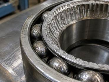
When this voltage discharges across the thin lubricating film in the bearings, it creates microscopic electrical arcs, a phenomenon known as electrical discharge machining (EDM). These arcs cause pitting, frosting, and eventually fluting (washboard-like grooves) on the bearing races and rolling elements. Over time, this damage degrades the lubricant, increases friction, and ultimately leads to premature bearing failure. The high-frequency parasitic currents generated by the VFD’s switching effectively turn the bearings into an unintended electrical pathway, significantly shortening their lifespan and contributing to costly downtime.
Why Installing AEGIS Prevents Synchronous VFD Failure in Heavy Industry
To combat this widespread issue, shaft grounding solutions are essential. These technologies provide a low-resistance path for harmful shaft currents to bypass the bearings and safely discharge to ground. Among the most effective solutions available are AEGIS shaft grounding rings, which utilize proprietary micro-fiber grounding technology. By diverting these destructive currents, AEGIS technology prevents electrical bearing damage, significantly extending motor life and reducing maintenance costs.
Implementing robust shaft grounding, such as with AEGIS products, is a critical step in ensuring the long-term reliability of multi-megawatt synchronous motors in heavy industrial applications. This proactive approach helps to maintain consistent operational performance, extend greasing intervals, and ultimately protect valuable assets from premature failure. Learn more about how AEGIS prevents synchronous VFD failure and safeguards your motor investments by exploring their comprehensive solutions.
Best Practices: How AEGIS Prevents Synchronous VFD Failure Through IEC Compliance
Effective bearing protection isn’t just about installing a device; it’s about adhering to industry best practices and standards. The IEC 61800-9-2 standard provides crucial guidelines for mitigating bearing currents in VFD-driven systems. Compliance with this standard involves a holistic approach, including:
- Proper shaft grounding continuity: Ensuring that the shaft grounding ring maintains continuous electrical contact with the motor shaft and effectively channels currents to the motor housing.
- High-potential (Hi-Pot) testing: Performing insulation tests to verify the integrity of the motor’s winding insulation, especially before integrating a VFD.
- Robust motor grounding path: Establishing a low-impedance path from the motor frame to earth ground, ensuring that any diverted currents can safely dissipate.
- Insulated non-drive end bearings: In some cases, insulating the non-drive end bearing can be a complementary measure to force shaft currents to flow through the drive end, where a grounding ring can then effectively divert them.
- Preventive maintenance protocols: Regularly monitoring bearing temperatures and vibration levels, and inspecting grounding ring integrity, are vital for early detection of potential issues.
Integrating these practices ensures that the VFD-driven synchronous motor system operates reliably and efficiently, minimizing the risk of electrical bearing damage.
Sizing, Commissioning, and Mitigation Protocols
Successfully deploying a VFD with a synchronous motor requires meticulous planning, precise sizing, and careful commissioning. This is particularly true when retrofitting a VFD onto an existing synchronous motor, which presents unique challenges such as ensuring compatibility with the motor’s original design, managing excitation systems, and addressing potential harmonic currents that can cause rotor heating.
For instance, when an LCI drive is used, a pony motor or starting cage is crucial. As LCIs rely on back-EMF for commutation, they cannot start a synchronous motor from standstill. The pony motor or starting cage must accelerate the rotor to typically 5–8% of synchronous speed before the LCI can take over and synchronize the motor.
Sizing a VFD for a synchronous motor application demands a comprehensive understanding of both the motor and the process it drives. Essential data includes:
- Motor nameplate electrical specifications: Rated voltage, current, power factor, speed, and frequency.
- Motor type: Field-wound (brush or brushless exciter), permanent magnet (PMSM), or synchronous reluctance (SynRM).
- Torque-speed curve: Detailed information on the motor’s torque capabilities across its operating speed range.
- Locked-rotor and pull-out torque: Critical for understanding starting and overload capabilities.
- Load inertia (WK²): The inertia of the driven equipment, essential for calculating acceleration and deceleration times.
- Exciter type and rating: For field-wound motors, the type (brush/brushless) and electrical characteristics of the exciter.
- Process speed envelope: The required minimum, maximum, and typical operating speeds of the application.
- Source impedance: For harmonic filter design and ensuring compliance with power quality standards like IEEE 519.
Commissioning a synchronous motor VFD installation is a multi-stage process that requires careful attention to detail to prevent common failure modes. Critical steps typically include:
- Pre-energization checks: Verifying insulation resistance, discharge resistor integrity, and exciter self-test functions.
- Static (motor uncoupled) tests: Confirming VFD parameters, control loop tuning, and excitation system response without mechanical load. This often includes autophasing for precise rotor position detection.
- Unloaded motor run: Operating the motor without load to verify speed control, current waveforms, and temperature. Forced ventilation may be needed for low-speed operation to prevent overheating.
- Loaded process run: Gradually applying the load and monitoring key performance indicators such as torque, speed, current, and temperature, ensuring stable operation across the required speed range.
- Performance verification: Documenting efficiency, power factor, and harmonic levels to ensure the system meets design specifications and regulatory requirements.
Common failure modes often stem from improper tuning of control loops, inadequate cooling at low speeds, or neglecting the impact of harmonics on the motor and grid. For multi-megawatt applications, while synchronous motors with VFDs (especially LCIs) can have higher initial costs and complexity compared to induction motor VFDs, their superior efficiency (often 0.3–0.5% higher), ability to provide unity or leading power factor for VAR support, and precise speed control often outweigh these factors. For example, a 9000 hp synchronous motor at 97.0% efficiency versus an induction motor at 96.5% efficiency can result in an annual energy difference of approximately 34 MWh (at 8000 hours/year), worth around $2,040/year at $60/MWh—a significant saving over the motor’s lifespan. With 30–40% of all new large drives in the multi-megawatt range now being delivered with synchronous machines, the benefits are clearly recognized across industries.
Here’s an essential list of motor and load parameters required for synchronous VFD sizing:
- Motor Rated Power (kW or hp)
- Motor Rated Voltage (V)
- Motor Rated Current (A)
- Motor Rated Speed (RPM)
- Motor Rated Frequency (Hz)
- Motor Power Factor
- Motor Exciter Type (Brush/Brushless)
- Exciter Voltage and Current Rating
- Motor Pole Number
- Motor Locked-Rotor Torque
- Motor Pull-Out Torque
- Motor Torque-Speed Curve
- Load Inertia (WK²)
- Load Torque-Speed Requirements
- Minimum and Maximum Operating Speeds
- Acceleration/Deceleration Time Requirements
- Ambient Temperature
- Cooling Method (e.g., TEFC, WPII, IC81W)
- Desired Power Factor at the Grid Connection
- Source Impedance (for harmonic analysis)
- Any Special Starting Requirements (e.g., soft start, full load start)
By addressing these critical aspects, industrial operations can harness the full potential of synchronous motor VFDs, achieving unparalleled efficiency, precision, and reliability in their most demanding applications.
Read more: https://namesvora.com/8-things-you-can-do-to-make-your-elderly-loved-one-more-comfortable/
https://namesvora.com/the-fabric-behind-the-fit-how-textile-innovation-is-changing-everyday-apparel/
https://namesvora.com/how-to-choose-the-right-fishing-boat-for-your-water-in-central-kentucky/